
- INTRODUCTION
- This technical description and instructions are designed for the study of the device, the safety measures, the operating and storage rules of UAV charge with direction action UA-50 (fig.1).
- In the technical description are accepted the following symbols:
- UAV charge with direction action UA-50
- Cable lines (jumper) – СЛ
- Electrodetonators quickmatch – electrodetonator ЭДП-р (or electrodetonator М-6)
- Remote control radio system – RCIS
- PURPOSE OF THE CHARGE
UAV charge with direction action UA-50 is designed to cause damage to the enemies softshell vehicles & manpower.
The charge consists of hull, shell with ready fragments, explosive charge (C4), intermediate charge RDX-А-IX-1, electro-detonator and bracket for attachment to the UAV.
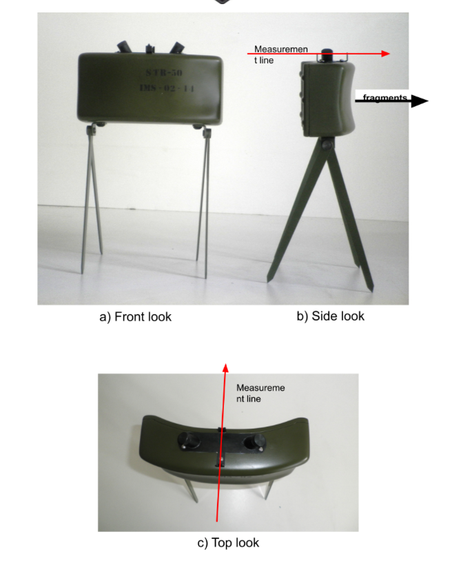
Fig.1. Remotely controlled charge with direction action UA-50
- TACTICAL AND TECHNICAL SPECIFICATIONS
- The charge contains ready fragments – steel cylinders ∅6х7mm, quantity – 700 pieces.
- The charge provides destruction in horizontal angle to 60О and distance 40m.
- The average probability of destruction in horizontal angle to 45О off to 40m is 0,56.
- In blast off to 30m the charge ensures destruction of softshell armored cars and unprotected manpower.
- The charge has no flying fragments in the occipital and lateral distance of 10m or more. Individual fragments from the body of the charge in the occipital direction are off to a distance of 20 meters.
- The charge is set to action by a remote control radio RCIS, autopilot, initiating board and detonator ЕДП-P (or М6).
- For group exploding the charges are connected in series with detonating cord and explosive capsules No8A on the ends. For fixing the cord with explosive capsule No8A in the fuse socket of the charge is used fitting bush.
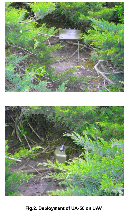
- The charge is set on the UAV by the help of brackets (fig.2).
- COMPOSITION OF THE CHARGE
Component | Quantity |
Remotely controlled charge with direction action UA-50 not finally projectile (fig.3) | 1 pc. |
Electro detonator ЭДП-р or М-6 (fig.4) | 1 pc. |
Fitting bushes (fig.4) | 2 pc. |
Cable lines (fig.4) | 20 m. |
Transportation bags for equipped charges (fig.4) | 1 pc. |
Remote control radio system RCIS-04 | 1 pc. for 5 pc. charges |
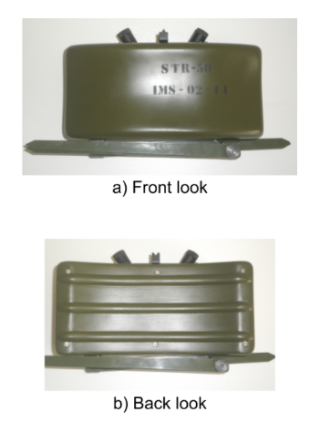
Fig.3. UA-50 in transportation mode
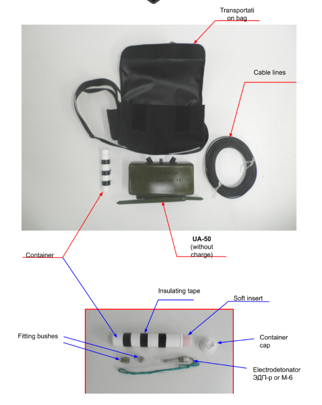
Fig.4. Components of the charge UA-50
- STRUCTURE AND OPERATION OF THE CHARGE
- UA-50 (fig.5) consists of plastic hull and top, fragmentation element and main explosive charge (С4). At the top of the hull there are two fuse sockets for detonators. In each slot is placed intermediate charge (compacted RDX-А-IX-1 with mass 2g) and the socket is closed by nut with gasket.
For placing the charge on the soil at the bottom of the hull are attached folding pins.
Fragmentation component of the charge is of cylinders ∅6х7mm in quantity 700 pieces.
The hull and the top are fastened together by screws.
The upper part of the hull has hit the target device to the charge towards the site for destruction, consisting of hindsight and foresight. The direction of the dispersion of the fragments is in the direction of the sight line of the target device.
The charge uses electro detonator ЭДП-р (or М6). The attachment of the electrodetonator М6 in the fuse socket is performed using fitting bush (fig.6).
Mass of the charge with the fragmentation element (steel cylinders ∅6х7mm – 700 pieces) – 2,20+0,05 kg.
For full charge is used:
🡺 explosive С4 of the main charge – 0,8 kg;
🡺 two pieces of moldings RDX-А-IX-1 each 0,002 kg;
Mass of the final charge – 3,0+0,05 kg.
Dimensions of the charge with folded pins:
🡺 length – 220 mm;
🡺 height – 130 mm;
🡺 width – 60 mm.
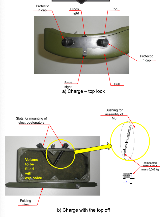
Fig.5. Structure of UA-50
- Principle of operation of the charge.
After charging with electro detonator ЭДП-р (or М6) and composition of the charge, detonation is realized via remote control system RCIS-04.
Fragments are distributed along the sight line of the target device.
- The container (fig.4) is intended for the packaging of electro detonator ЭДП-р (or М6). The container consists of a plastic cup, and a soft insert. In the container are put 2 pieces of fitting bushes (fig.6). Over the container are wound three rows insulating tape (fig.4) for use in connection of wires to the electrodetonator to the cable line.
Overall dimensions of the container:
🡺 diameter – 30 мм;
🡺 length – 150 мм;
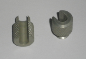
Fig.6. Fitting bushes for electro detonator М-6
and blasting caps No8A
- The bag (fig.7) is intended for conveying the charge set. The bag has compartments (pockets) for the charge, cable line and container with electro detonator ЭДП-р or М6 (fig.4).
Mass of the bag with the cable line – 0,650 kg.
Mass of the bag with the charge UA-50 and cable line – 3,650+0,100 kg.
Dimensions of the bag:
🡺 length – 320 mm;
🡺 height – 180 mm;
🡺 width – 90 mm;
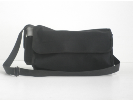
Fig.7. Transportation pack for assembled charge
- PACKAGE OF THE CHARGE
In army bases and in warehouses the charges and the completing components arive and are stored in plastic cases with the following:
Component | Quantity |
Remotely controlled charges with direction action UA-50 (without charges) | 10 pc. |
Containers for electro detonators | 10 pc. |
Fitting bushes | 20 pc. |
Cable lines (х20m) | 10 pc. |
Transportation bags for equipped charges | 10 pc. |
- MARKING AND SEALING
- On the top of the charge UA-50 applies marking indicating: the manufacturer, the party number, year of manufacture.
- On the case are applied markings indicating:
– name of the charge
– manufacturer, the party number, year of manufacture.
– INERT sign for no charged products;
– total mass, kg;
– volume, m3.
- The sealing of the case with the products is made with seal bearing the number of quality control officer of the manufacturer.
- When packaging in the army warehouses, on the case are further added signs indicating the code and quantity of products packed, lot number, month and year of packaging.
- 8. SAFETY PRECAUTIONS INSTRUCTIONS
- Before starting work with the charges it is needed to carefuly read the technical description and the operating manual of the charge UA-50.
- All operations for filling the charge must be carried out strictly in accordance with instructions for handling explosive materials and products.
- Incomplete charge and completing components are safe during transport and storage.
- The transportation of the charge and the completing components to the site can be done in plastic cases, in which are sorted all elements completing the charge.
- ORDER OF COMPOSITION OF THE CHARGE
- Select a location to place the charge.
- Take out the charge of the bag or container.
- Untie the pins of the charge and stretch them so as to ensure the sustainability of the charge.
- Remove the protective cap from one of ignition nests of the charge.
- Take the electro detonator ЭДП-р (or М6) out of the container and set it in one of the ignition nests of the charge (fig.8). When installing the electro detonator М6 is used fitting bush (fig.6).
- Set the charge steady on the selected location.
- Target the charge using the target device so that the hidsight and front sight to match the desired area of injury to the expected object (fig.8).
- The charge is connected with the system for remote activation RSIS-04 via cable line.
- In detonation of several charges at a time for connection between them is used detonating cord, blasting caps No8A and fitting bushes (fig.6).
- The charge, activating group of charges is connected with the system for remote activation RSIS-04 via cable line.
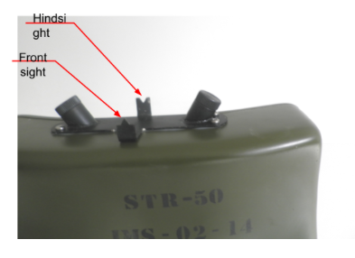
Fig.8. Targeting device of UA-50
- STORAGE RULES
- In warehouses and in army bases the charges and the completing components arive in their own pack and are stored in it.
- Storage warranty – 10 years.
- The control over the condition of the charges and the completing components in warehouses and in army bases is conducted in accordance with the effective instructions for quality control status of the engineering ammunitions.
- TRANSPORTATION
The charges and the completing components are transported from the от factory to the warehouses in plastic bags with all modes of transport in accordance with existing rules for carrying ammunition.
- INTRODUCTION
- This technical description and instructions are designed for the study of the device, the safety measures, the operating and storage rules of UAV charge with direction action UA-50 (fig.1).
- In the technical description are accepted the following symbols:
- UAV charge with direction action UA-50
- Cable lines (jumper) – СЛ
- Electrodetonators quickmatch – electrodetonator ЭДП-р (or electrodetonator М-6)
- Remote control radio system – RCIS
- PURPOSE OF THE CHARGE
UAV charge with direction action UA-50 is designed to cause damage to the enemies softshell vehicles & manpower.
The charge consists of hull, shell with ready fragments, explosive charge (C4), intermediate charge RDX-А-IX-1, electro-detonator and bracket for attachment to the UAV.
Fig.1. Remotely controlled charge with direction action UA-50
- TACTICAL AND TECHNICAL SPECIFICATIONS
- The charge contains ready fragments – steel cylinders ∅6х7mm, quantity – 700 pieces.
- The charge provides destruction in horizontal angle to 60О and distance 40m.
- The average probability of destruction in horizontal angle to 45О off to 40m is 0,56.
- In blast off to 30m the charge ensures destruction of softshell armored cars and unprotected manpower.
- The charge has no flying fragments in the occipital and lateral distance of 10m or more. Individual fragments from the body of the charge in the occipital direction are off to a distance of 20 meters.
- The charge is set to action by a remote control radio RCIS, autopilot, initiating board and detonator ЕДП-P (or М6).
- For group exploding the charges are connected in series with detonating cord and explosive capsules No8A on the ends. For fixing the cord with explosive capsule No8A in the fuse socket of the charge is used fitting bush.
- The charge is set on the UAV by the help of brackets (fig.2).
- COMPOSITION OF THE CHARGE
Component | Quantity |
Remotely controlled charge with direction action UA-50 not finally projectile (fig.3) | 1 pc. |
Electro detonator ЭДП-р or М-6 (fig.4) | 1 pc. |
Fitting bushes (fig.4) | 2 pc. |
Cable lines (fig.4) | 20 m. |
Transportation bags for equipped charges (fig.4) | 1 pc. |
Remote control radio system RCIS-04 | 1 pc. for 5 pc. charges |
Fig.3. UA-50 in transportation mode
Fig.4. Components of the charge UA-50
- STRUCTURE AND OPERATION OF THE CHARGE
- UA-50 (fig.5) consists of plastic hull and top, fragmentation element and main explosive charge (С4). At the top of the hull there are two fuse sockets for detonators. In each slot is placed intermediate charge (compacted RDX-А-IX-1 with mass 2g) and the socket is closed by nut with gasket.
For placing the charge on the soil at the bottom of the hull are attached folding pins.
Fragmentation component of the charge is of cylinders ∅6х7mm in quantity 700 pieces.
The hull and the top are fastened together by screws.
The upper part of the hull has hit the target device to the charge towards the site for destruction, consisting of hindsight and foresight. The direction of the dispersion of the fragments is in the direction of the sight line of the target device.
The charge uses electro detonator ЭДП-р (or М6). The attachment of the electrodetonator М6 in the fuse socket is performed using fitting bush (fig.6).
Mass of the charge with the fragmentation element (steel cylinders ∅6х7mm – 700 pieces) – 2,20+0,05 kg.
For full charge is used:
🡺 explosive С4 of the main charge – 0,8 kg;
🡺 two pieces of moldings RDX-А-IX-1 each 0,002 kg;
Mass of the final charge – 3,0+0,05 kg.
Dimensions of the charge with folded pins:
🡺 length – 220 mm;
🡺 height – 130 mm;
🡺 width – 60 mm.
Fig.5. Structure of UA-50
- Principle of operation of the charge.
After charging with electro detonator ЭДП-р (or М6) and composition of the charge, detonation is realized via remote control system RCIS-04.
Fragments are distributed along the sight line of the target device.
- The container (fig.4) is intended for the packaging of electro detonator ЭДП-р (or М6). The container consists of a plastic cup, and a soft insert. In the container are put 2 pieces of fitting bushes (fig.6). Over the container are wound three rows insulating tape (fig.4) for use in connection of wires to the electrodetonator to the cable line.
Overall dimensions of the container:
🡺 diameter – 30 мм;
🡺 length – 150 мм;
Fig.6. Fitting bushes for electro detonator М-6
and blasting caps No8A
- The bag (fig.7) is intended for conveying the charge set. The bag has compartments (pockets) for the charge, cable line and container with electro detonator ЭДП-р or М6 (fig.4).
Mass of the bag with the cable line – 0,650 kg.
Mass of the bag with the charge UA-50 and cable line – 3,650+0,100 kg.
Dimensions of the bag:
🡺 length – 320 mm;
🡺 height – 180 mm;
🡺 width – 90 mm;
Fig.7. Transportation pack for assembled charge
- PACKAGE OF THE CHARGE
In army bases and in warehouses the charges and the completing components arive and are stored in plastic cases with the following:
Component | Quantity |
Remotely controlled charges with direction action UA-50 (without charges) | 10 pc. |
Containers for electro detonators | 10 pc. |
Fitting bushes | 20 pc. |
Cable lines (х20m) | 10 pc. |
Transportation bags for equipped charges | 10 pc. |
- MARKING AND SEALING
- On the top of the charge UA-50 applies marking indicating: the manufacturer, the party number, year of manufacture.
- On the case are applied markings indicating:
– name of the charge
– manufacturer, the party number, year of manufacture.
– INERT sign for no charged products;
– total mass, kg;
– volume, m3.
- The sealing of the case with the products is made with seal bearing the number of quality control officer of the manufacturer.
- When packaging in the army warehouses, on the case are further added signs indicating the code and quantity of products packed, lot number, month and year of packaging.
- 8. SAFETY PRECAUTIONS INSTRUCTIONS
- Before starting work with the charges it is needed to carefuly read the technical description and the operating manual of the charge UA-50.
- All operations for filling the charge must be carried out strictly in accordance with instructions for handling explosive materials and products.
- Incomplete charge and completing components are safe during transport and storage.
- The transportation of the charge and the completing components to the site can be done in plastic cases, in which are sorted all elements completing the charge.
- ORDER OF COMPOSITION OF THE CHARGE
- Select a location to place the charge.
- Take out the charge of the bag or container.
- Untie the pins of the charge and stretch them so as to ensure the sustainability of the charge.
- Remove the protective cap from one of ignition nests of the charge.
- Take the electro detonator ЭДП-р (or М6) out of the container and set it in one of the ignition nests of the charge (fig.8). When installing the electro detonator М6 is used fitting bush (fig.6).
- Set the charge steady on the selected location.
- Target the charge using the target device so that the hidsight and front sight to match the desired area of injury to the expected object (fig.8).
- The charge is connected with the system for remote activation RSIS-04 via cable line.
- In detonation of several charges at a time for connection between them is used detonating cord, blasting caps No8A and fitting bushes (fig.6).
- The charge, activating group of charges is connected with the system for remote activation RSIS-04 via cable line.
Fig.8. Targeting device of UA-50
- STORAGE RULES
- In warehouses and in army bases the charges and the completing components arive in their own pack and are stored in it.
- Storage warranty – 10 years.
- The control over the condition of the charges and the completing components in warehouses and in army bases is conducted in accordance with the effective instructions for quality control status of the engineering ammunitions.
- TRANSPORTATION
The charges and the completing components are transported from the от factory to the warehouses in plastic bags with all modes of transport in accordance with existing rules for carrying ammunition.
- CHARGE FUNCTION
The directional fragmentation charge “UA-100 ” is designed to inflict casualties on the enemy and delivered by UAV .
Figure 1 presents charge general view.
The charge consists of a body equipped with fabricated fragments, boosting charge (TNT- ), explosive charge (TNT- ), electric detonator (EDPr ) and positioning device.
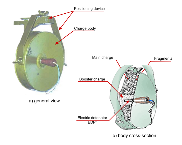
Fig.1. Directional fragmentation charge ”UA-100 ”
- CHARGE SET
The delivery set of the charge “UA-100 ” contains:
COMPONENT PART | QUANTITY |
Charge “UA-100 ” | 1 pc. |
Electric detonator “EDPr ” | 1 pc. |
Positioning device: – Console – Bracket |
1 pc. 1 pc. |
- PERFORMANCE DATA OF “UA-100 ”
Charge body material | steel | |
Charge body overall dimensions | ∅236 х 82.5 mm | |
Main charge weight | 2.4 kg | |
Booster charge weight | up to 0.160 kg | |
Quantity of fragments (steel rollers ∅10х10mm) |
| |
Total weight of filled charge body | 5.8 kg | |
Distance of fragment flight | up to 160 m | |
Width of casualty area | from 6.5 to 9.5 m | |
Operation temperature range | from -50 to +50 оС | |
Storage temperature range | from -50 to +60 оС | |
Manner of laying | UAV |
- CHARGE UAUCTURE
4.1. Figure 2 presents the structure of charge “UA-100 ”. The charge body is made of stamped sheet steel. The front and back body walls have cone shape. On the front wall there is a threaded bed for electric detonator “EDPr ”, which is covered by protection cap during storage.
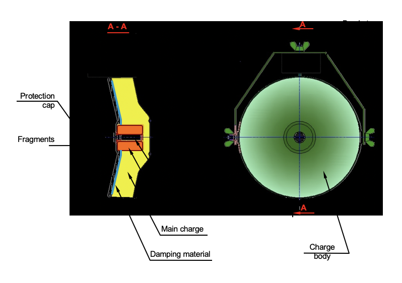
Fig.2. UAucture of charge “UA-100 ”
The body inner volume is separated into two parts by a barrier of damping material.
Between the damping material barrier and the body front wall (Fig.2) there are placed in a single row fabricated material, covered by resin in order to avoid their disarrangement.
Between the barrier and the body back wall there is placed the main charge – 50/50-RDX/ material. In the main charge center the booster charge lies – material.
On the body sidewall surface there are welded two slats with screws and butterfly nuts for fixing the charge body to the positioning device (see Fig. 3-item 4.2).
4.2. The charge positioning device (Fig.3) consists of a console and a bracket. The sharp end of the console is driven into a place suitable to position the charge. In one of the console ends there are made two mutually perpendicular conic holes for attaching the bracket.
In the middle of the bracket there is fixed a cut narrow pipe with a bolt, on which a butterfly nut is screwed. The bolt has a cone tip. When the butterfly nut is tightened, the bolt cone tip enters into the cut narrow pipe and presses it to the console cone hole. On both ends of the bracket there are holes in which the screws welded to slats on the charge enter (Fig.2). The bracket is tightened to the charge by means of butterfly nuts.
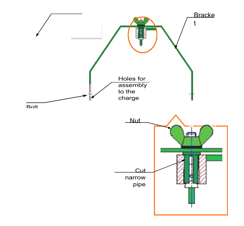
Fig.3. Charge positioning device
- CHARGE PRINCIPLE OF OPERATION “UA-100”
When electrical impulse is delivered to the electric detonator it explodes and causes detonation in the boosting pressing and in the main charge (Fig.2). The fragments (400–pcs.) fly in direction of the sighting.
Figure 4 shows the distribution of the UA-100 casualty areas. The numbers 0.1; 0.5; 0.9 and 1.0 show the casualty probabilities in the different zones of charge operation range.
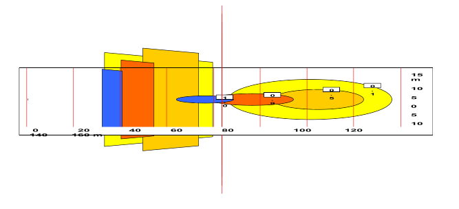
Fig.4. Diibution of “UA-100” casualty areas
- PACKING, STORAGE AND TRANSPORTATION
In transportation condition the bracket of the positioning device is mounted to the charge body (Fig.2). The charges are packed in wooden boxes, 5 pieces in each one, with the corresponding set of consoles for their positioning. The packing is performed in compliance with Fig.5.
The electric detonators (EDPr – ) are packed in polyethylene pocket and transported separately in wooden box.
The packed charges could be carried by any type of transport.
The charges are stored in dry premises that meet all the requirements for storage of ammunitions, in their transportation packing.
Fig.5. Transportation packing of “UA-100 ”
- 7. SAFETY MEASURES
All manipulations with the charges and the electric detonators should be carried out under strict observation of the safety requirements ordered by the adequate normative documents for handling ammunitions and land-based charges.
The personnel in charge of these activities should be instructed and introduced to the charge structure and principle of operation as well as to the required safety measures.
When handling the charges it is necessary to observe strictly the order and precisely fulfill the respective instructions, described in the present manual.
- CHARGE PREPARATION AND LAYING
When laying the charges “UA-100 ”, the following operations are carried out:
- Connect the initiating board to the autopilot. Make sure it is programmed to the RC proper switch “Armed”.
- Install console of the positioning device into a UAV, or other object acting as a support for charge laying. Figure 6а presents charge positioning on a vertical beam.
- Attach the charge body to the UAV bracket in the required direction and tighten the butterfly nuts so that the charge cannot be rotated.
- Fix the bracket, together with the charge, in one of the holes of the console and screw the butterfly nut.
- Direct the charge by means of a sighting device. For charge aiming a sighting device (see item 9 – Fig.7)
- Tighten finally the butterfly nuts and check once more the aiming accuracy.
- Check the running order of the initiating board (autopilot or etc) and the electric detonator.
- Unscrew the protective cap on the charge from the threaded bed and screw in it the electric detonator.
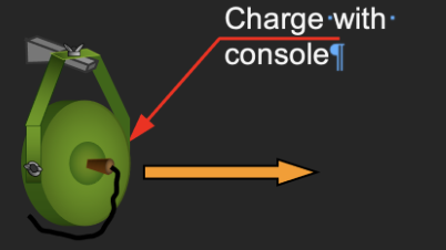
Fig.6. Positioning of “UA-100 ”
- Connect the electric detonator to the blasting circuit and insulate the connections.
- After the personnel has withdrawn from the UAV with installed charges, check the serviceability of the charges electric circuits from the autopilot.
9 CHARGE NEUTRALIZATION
In order to neutralize the charge it is necessary to perform the following operations:
9.01 Disconnect the voltage source of the initiating board from the authopilot unit and shorten the wire ends.
9.02 Unscrew the electric detonator from its threaded bed and remove it from the charge.
9.03 Disconnect the electric detonator wires from the initiating board.
9.04 Remove the charge from the positioning device.